Theo Verelst DSP Page
last
update: juli 30 2004
Because of my recent
projects with Blackfin DSP's, I though it about time to make a page
about some of my makings, and make some open source projects available
for download.
Ananlog Devices has a familiy of
Digital Signal Processor chips called blackfin
, which are small, relatively low power, 16/32 bit
mostly over a GigaOperation per second risc-type DSPs, and also makes
evaluation kits available for reasonable prices, which include a
development environment with C compiler graphical interactive design
environment, and examples.
My first publically available project is for the BF561 dual-core 500
MHz blackfin on a EZLITE board, with the standards version
3.5
(june 2004) development environment. Without question, parts can be
used for the BF533 single core DSP and EZLITE as well, and in fact most
of the code (in this case maybe all) is in C so it could prove usefull
in various ways.
The first project is a CHORUS UNIT
mainly with the musicians association of making a musical instrument
like an electrical piano, a guitar or a synthesizer sound fatter, more
pleasing by adding slowly varying delayed signals ot the original
stereo signal. The board is used like with the audio pass through
example, which makes use of the excellent AD/DA channels, in this case
only input and output 0.
I"ve made the project a flash project, so it boots in the BF561 at
startup, in principle in dual core more, though core B only idles at
the moment, including setting up the DRAM and the LEDS. The main
processing I programmed happens in
init.c
process_data.c
In init.c a sine table is made in DRAM, which is used by the sound
chips interupt routine in process_data.c, where variable delays have
been programmed.
As a bonus, my one-day project has been given a late night stereo LED VU METER
which is a near perfect Peak meter with immedeate response to the
signal, without missing a sample, and gradual meter response in
downward sense, so peaks fade away slowly. Of course I make use of the
two rows of 8 LEDS, with DB meanings of something like: -3bB -6dB -9dB
-12dB -18dB -24dB -36dB -48dB . Works neat.
I didn't do a processor use analysis, the BF561 I can luckily use is
officially a 500 MHz 0.2 version, which runs this fine, and has been
given a 500MHz clock.
I've zip-ed the whole project in some working version for
non-commercial download here:
Chorus / LED VU Unit (ZIP
file, 150kB)
Let me know if it works for you! And please inform me if you spread any
modified versions, which is permitted, but my original notice and
address must stay in place.
It's a prototype, and not perfect in all ways: the higher frequencies
in the signal with the current crude delay line modulation make a lot
of audible additional noise... But it's a rich, 3-way chorus
effect, you may want to try changing the modulation depth and
frequencies in process_data and initsinewave .
I've now ported the same to the BF533
EZLITE, for which the project files are available here:
Stereo Chorus, flash version
(ZIP file, 178 kB)
I found this example for the BF533 on making a PAL output test signal
at the Blackfin Forum
030439-11.zip
I've recently made a 'wiki' page on the integrated Tcl within VisualDSP
VisualDSP builtin Tcl use
, because I find Tcl (and it's graphical extension Tk) an
inportant and handy language. Unfortunately, visualdsp doesn't allow as
much Tcl interaction as I'd prefer, like for opening mulitple
subprojects projects.
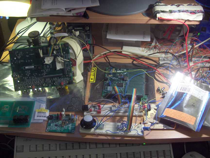
A view of the boards in prototype use (for audio applications, see
also My audio page )
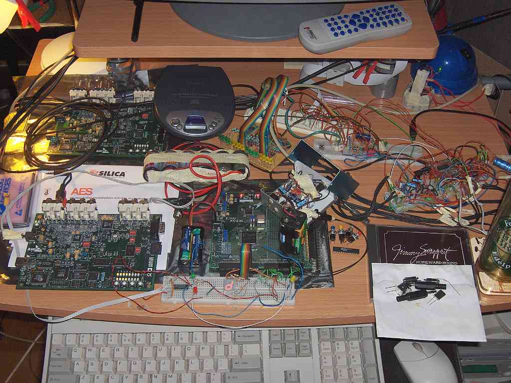
Interface between Blackfin 533 EZlite and a Xilinx CoolrunnerII
demo board
See my Xilinx page for the xilinx programming
files, this project:
Visual DSP project files,
WINZIP format
contains a prototype audio filter application (its a chorus at the
moment) which real-time interfaces with the Xilinx and some knobs and
displays connected to it.
I've made connections between some bus lines and 8 bits of the data
bus and some address lines of the blackfin EZLITE backside bus (the DSP
bus) with 0.5KOhm resistors plugged in the connector, and then fed to a
wire into a connector into the Xilinx board, See the Xilinx pin
definition file and the EZLITE schemetics for the names (I've prepended
a 'N' for 'not')..
Making the connections is doable, but you have to have experience
with contempotary CMOS electronics, and be aware of the riscs of
connecting something to the live DSP bus wires! I've made a 1/10 inch
connector (with general purpose PCB with connector pins) with a little
piece of flexible flat cable for the Xilinx demo board side, which I
remove first, after grounding myself, then I start the Dsp board and
the Xilinx board, connect the ground, stop the DSP and then I slide in
the connector to start things up for the prototype connection, where
both boards have seperate supplies.
I've made a movie about the operation of the combination and the
working turnable and press knobs and the counting display and a letter
on the 5x7 display:
window media format movie about
the project, english comments by the author, 250MByte total.
home page [2]
email: theover@tiscali.nl [2] message directly to site maintainer